
Overview
Eight matched 10-µA outputs in three CMOS technologies.
Physical sign-off
DRC, LVS, antenna, density, latch-up and matched-layout checks.
Reliability review
Electromigration, IR drop, redundant supply vias and gate-oxide voltage.
Extracted-layout verification
PVT, 200-run Monte Carlo and schematic-to-layout comparison.
| Measure | 65-nm bulk | 22-nm FD-SOI | 16-nm FinFET |
|---|---|---|---|
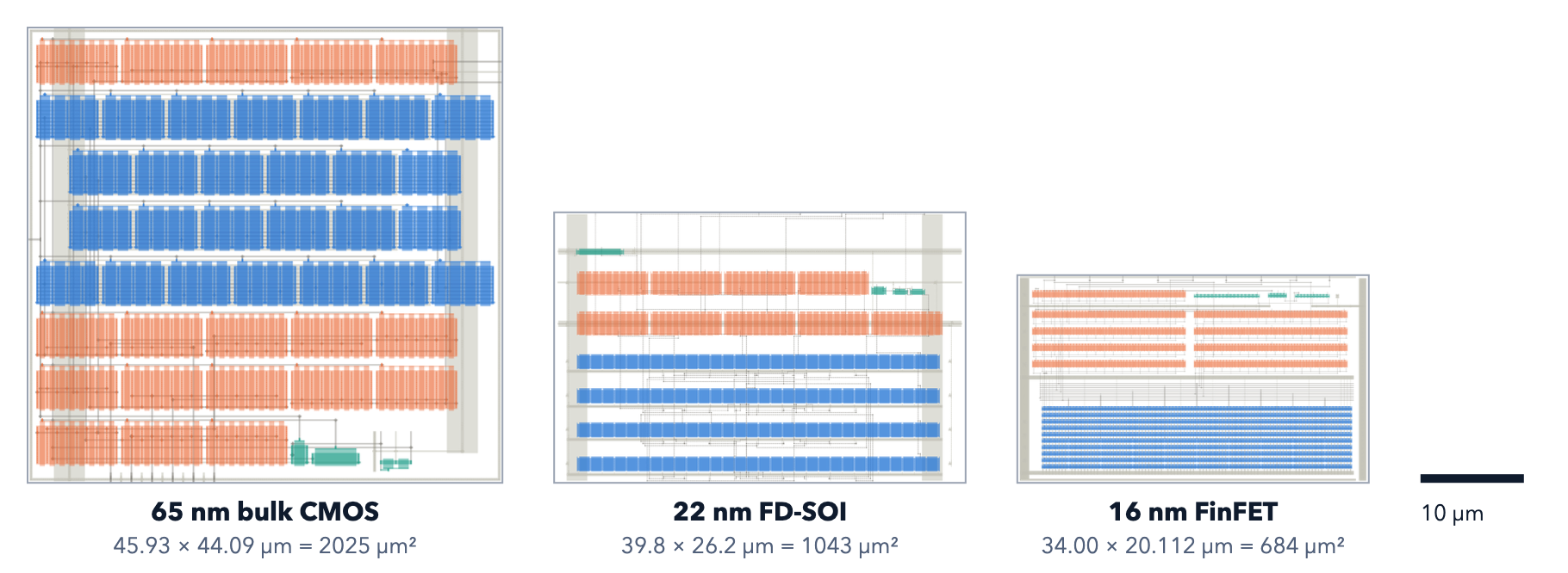
| Macro area | 2,025 µm² | 1,043 µm² | 684 µm² |
| Output matching, worst 1σ | 1.14% | 1.15%¹ | 1.24% |
| Output drop at 0.2 V | 0.66% | 1.22% | 1.40% |
| Own power, typical | 1.57 µW | 0.87 µW | 0.96 µW |
¹The 22-nm design basis uses the best-case matching model; the worst-case model gives 1.94%.
Verification
Designer-directed implementation and documented gate scope.
| Check | 65 nm | 22 nm | 16 nm |
|---|---|---|---|
| Physical checks: DRC/LVS/antenna/density/latch-up | Pass | Pass¹ | Pass¹ |
| Matching layout: centroid/dummies/coverage | Pass | Pass | Pass |
| Reliability: EM/IR/vias/oxide | Pass | Pass | Pass² |
| Extracted-layout PVT and 200-run Monte Carlo | Pass | Pass | Pass |
| Schematic-to-layout comparison | Pass | Pass | Pass |
¹Multi-patterning colouring was not run at 22/16 nm. ²16-nm electromigration used estimated limits. These are block-level sign-off records, not silicon measurements.
Function & specification
One reference current becomes eight matched bias currents.
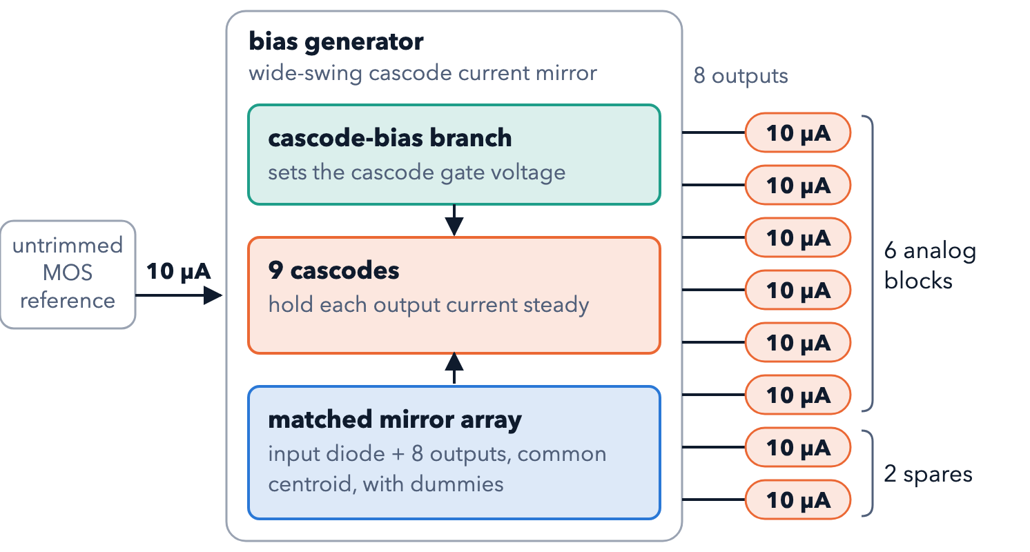
| Requirement | Target |
|---|---|
| Supply | 65 nm: 1.2 V; 22 and 16 nm: 0.8 V; all ±5% |
| PVT box | 5 process corners × 0 / 27 / 85 °C × supply ±5% = 45 points |
| Outputs | 8 × 10 µA; each within 2% down to 0.2 V on its pin |
| Output-to-output matching | 1σ ≤ 3% (Monte Carlo) |
| DC supply rejection | ≥ 35 dB |
Transistor schematic
One wide-swing cascode mirror, process-specific device sizing.
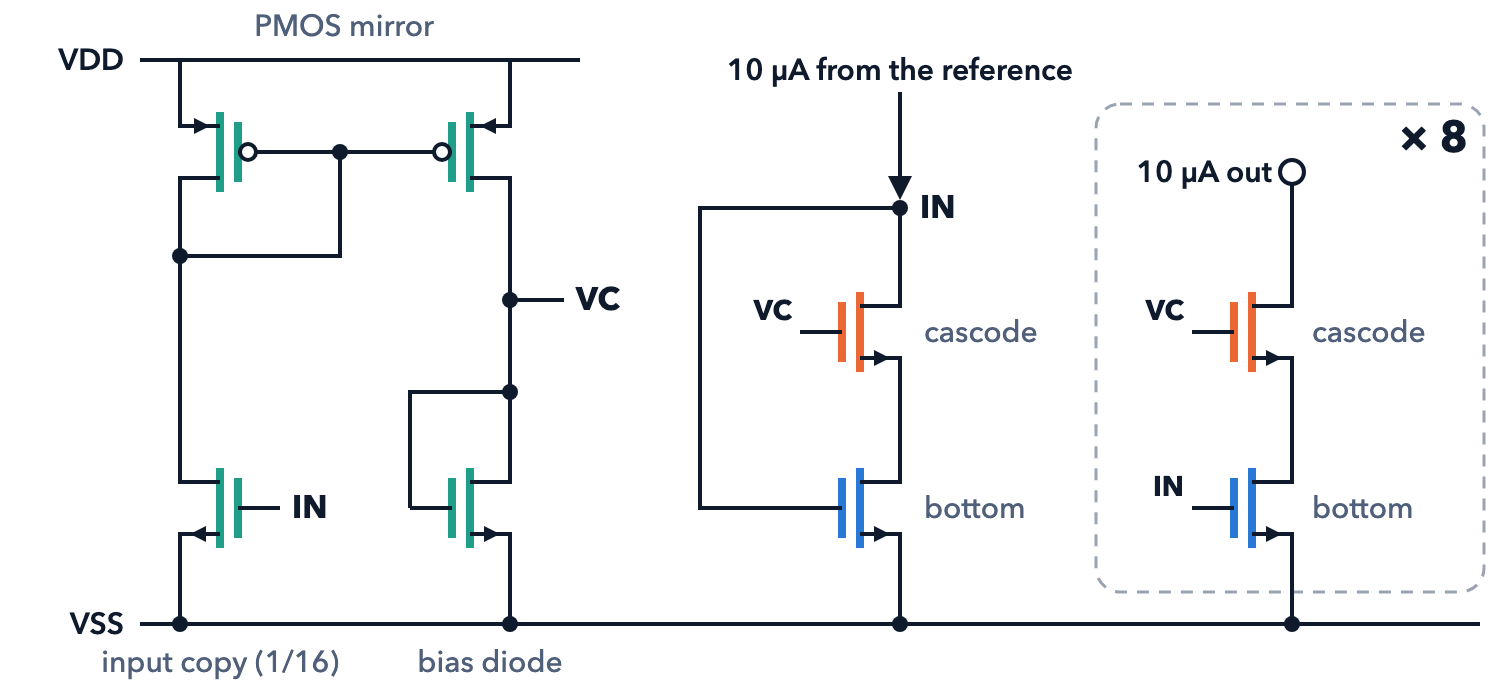
| Device group | 65 nm | 22 nm | 16 nm |
|---|---|---|---|
| Bottom devices | 30 / 1 µm, 2 × 4 fingers | 10 / 1 µm, 4 × 2 fingers | 16 × 6 fins, 5 × 192 nm |
| Cascodes | 60 / 0.5 µm, 2 × 8 fingers | 20 / 0.5 µm, 10 fingers | 204 fins, 3 × 168 nm |
| Input copy (1/16) | 1.875 / 1 µm | 0.625 / 1 µm | 6 fins, 5 × 192 nm |
| PMOS mirror | 0.4 / 1 µm | 0.4 / 1 µm | 4 fins, 5 × 192 nm |
| Bias diode | 1.1 / 4 µm | 0.4 / 4 µm | 4 fins, 17 × 240 nm |
Layouts
Signed-off macros shown at one scale.
Matched arrays
Symmetric placement with dummies and equal device surroundings.
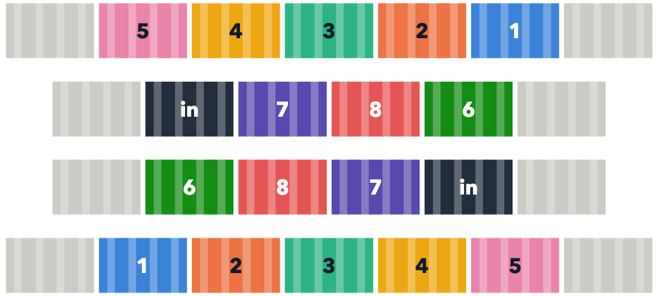
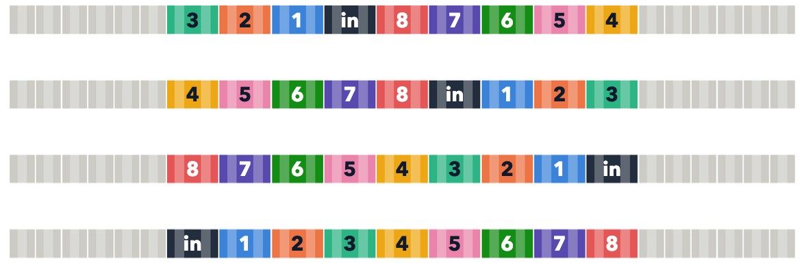
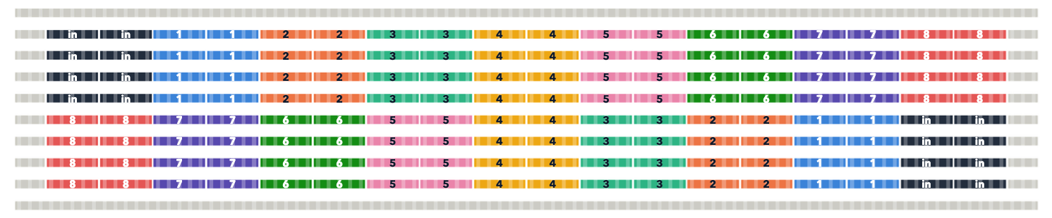
Each output’s units share one drain net; the array map was checked against the drawn connectivity.
Complete results
Post-layout values; worst over 45 PVT points unless noted.
| Measure | 65 nm | 22 nm | 16 nm |
|---|---|---|---|
| Area | 2,025 µm² | 1,043 µm² | 684 µm² |
| Supply (±5%) | 1.2 V | 0.8 V | 0.8 V |
| Outputs | 8 × 10 µA | 8 × 10 µA | 8 × 10 µA |
| Matching, worst output 1σ¹ | 1.14% | 1.15%² | 1.24% |
| Systematic copy error | 0.28% | 0.071% | 0.154% |
| Minimum output resistance | 10.5 MΩ | 12.2 MΩ | 8.2 MΩ |
| Current drop at 0.2 V | 0.66% | 1.22% | 1.40% |
| DC PSRR, ideal input | 63.0 dB | 93.2 dB | 79.5 dB |
| DC PSRR, with reference³ | 51.2 dB | 42.6 dB | 41.3 dB |
| Own power, typical⁴ | 1.57 µW | 0.87 µW | 0.96 µW |
¹200-run extracted-layout Monte Carlo, typical corner, 27 °C. ²Best-case matching model; worst-case 1.94%. ³Reference source is schematic at 22/16 nm, both extracted at 65 nm. ⁴Bias branch only; eight output currents excluded.
Matching
Output-to-output 1σ, one point per output.
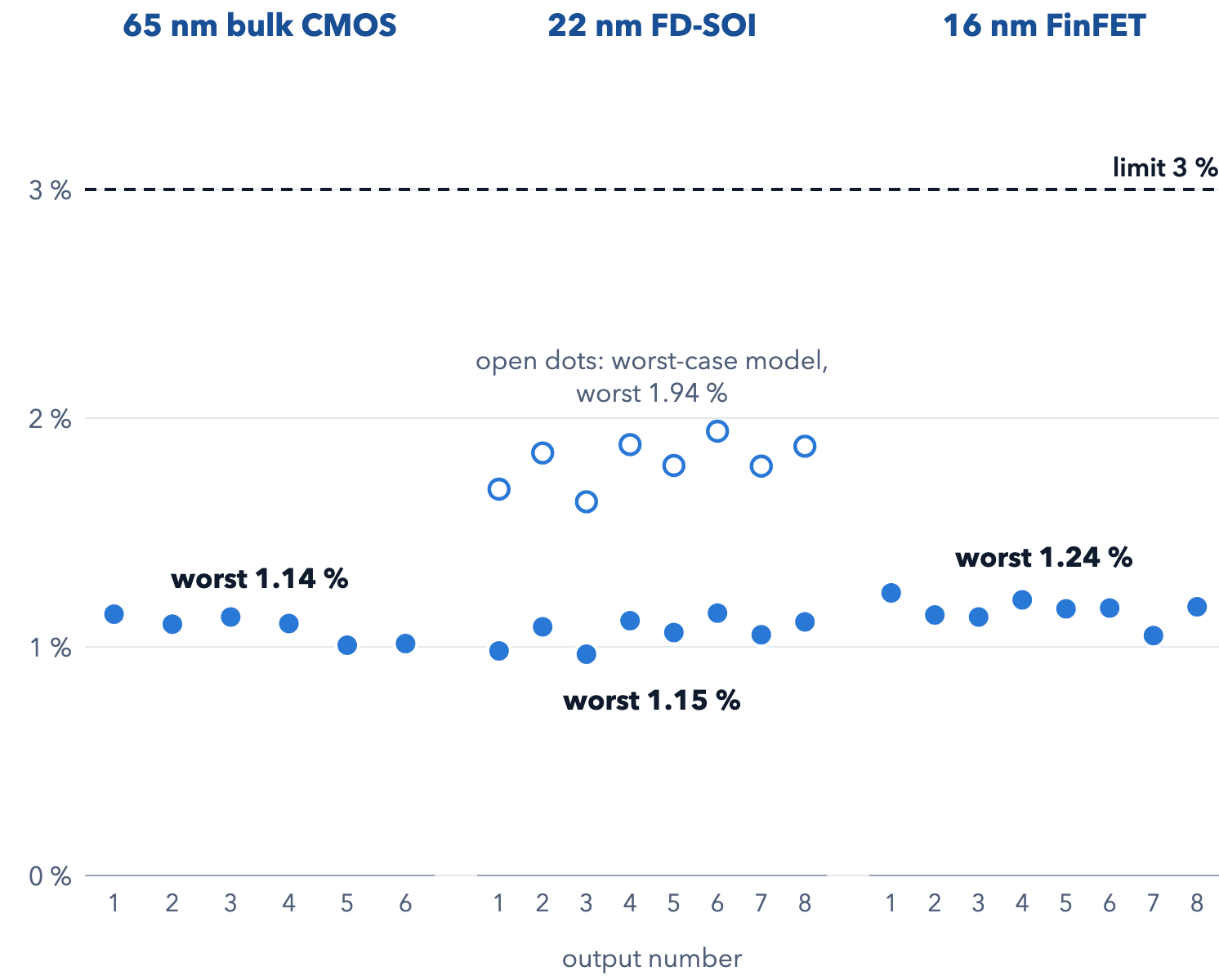
The 65-nm bench included six consumer-loaded outputs; the 22-nm and 16-nm benches included all eight. The target was ≤3%.
Output-voltage sweep by technology
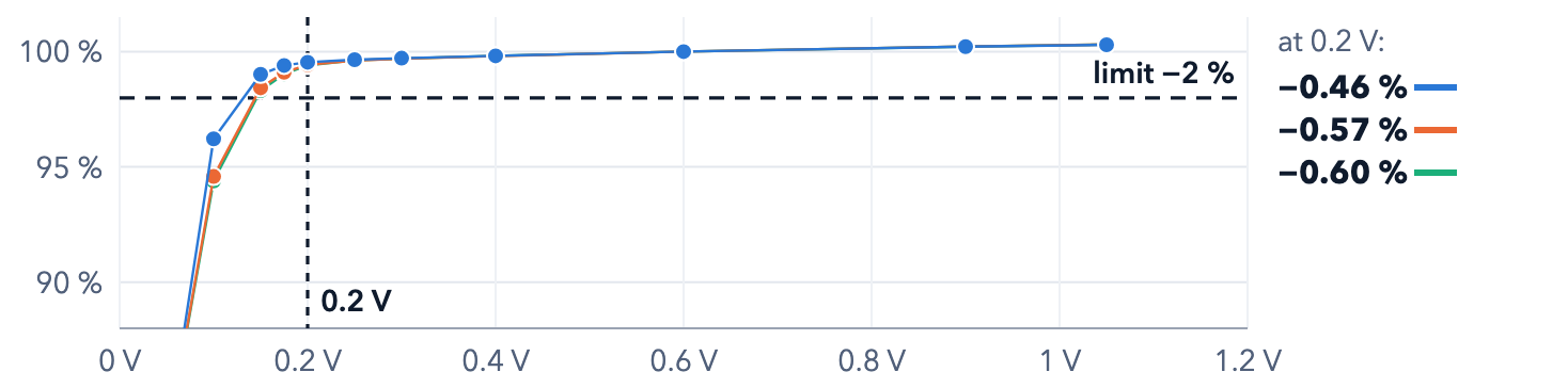
One output per plot, swept from 0 V to the supply; output current is normalized to its value at mid-supply.
65-nm bulk CMOS
22-nm FD-SOI
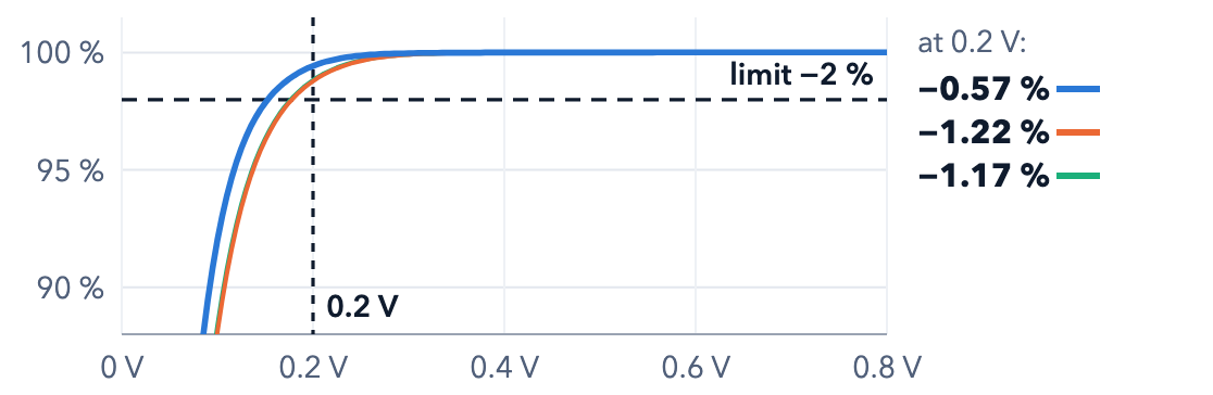
16-nm FinFET
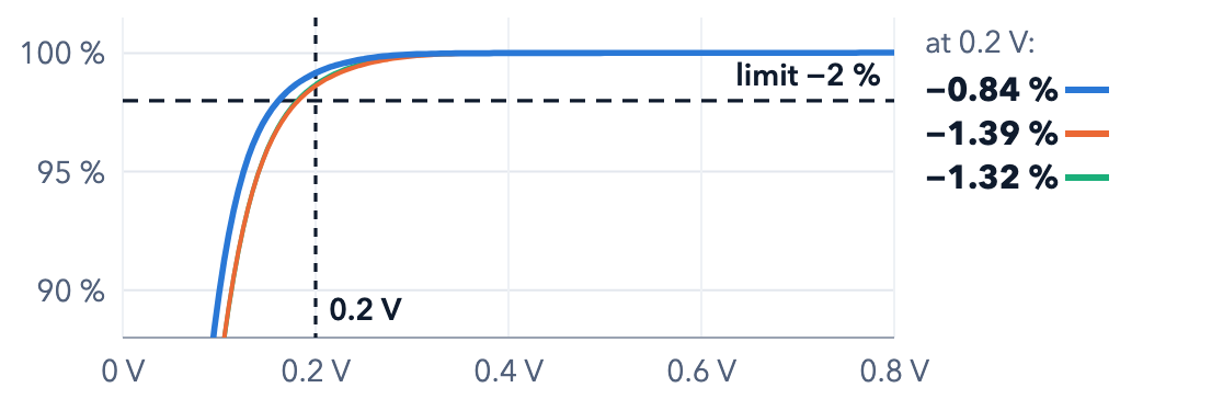
Worst drop at 0.2 V across all 45 PVT points: 0.66%, 1.22% and 1.40% for 65, 22 and 16 nm, respectively. The acceptance target is no more than 2% below the mid-supply current.
Supply rejection
Both the isolated block and the reference-fed chain matter.
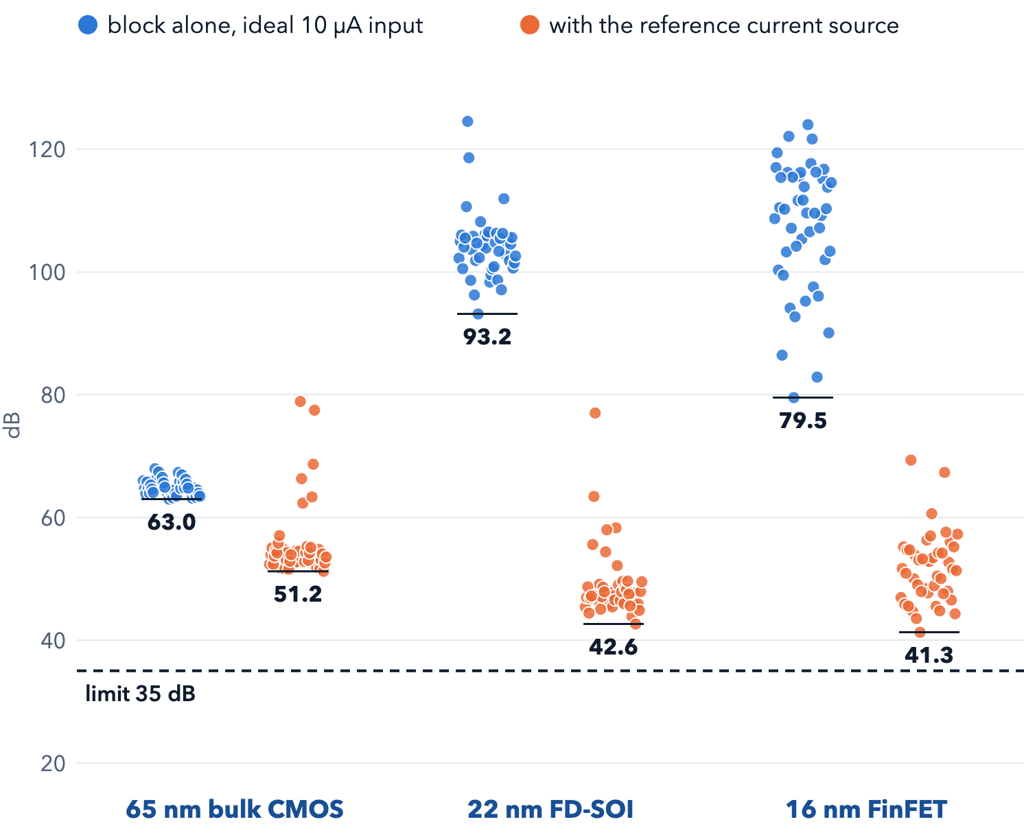
Worst block-alone PSRR: 63.0 / 93.2 / 79.5 dB (65 / 22 / 16 nm). With the reference: 51.2 / 42.6 / 41.3 dB. The acceptance target was ≥35 dB.